Vehicle Control System Design Environment
Model-based environment for developing real-time automotive control systems on a unified DriveOS platform
Drako Design Environment (DDE) enables automotive engineers to design and deploy high-performance control systems directly from Simulink models. This model to deployment workflow eliminates embedded coding, cross-compilation, and manual OS-level integration work.
Engineers define behavior visually, while DDE automates scheduling, domain mapping, communication, and deployment. To further accelerate programs, teams can leverage Drako’s production-ready hardware and software reference implementations as reusable starting points.
This combination dramatically reduces development effort, allowing engineers to focus on control functionality and vehicle performance instead of low-level infrastructure.

Model-Based Design Without Embedded Coding
Drako Design Environment (DDE) enables automotive OEMs to develop control systems entirely within Simulink — without writing embedded C code, configuring hardware interfaces, or managing real-time OS details. DDE automatically implements the infrastructure, integration, and deployment pipeline, allowing engineers to focus purely on system behavior using functional blocks and signal flows. This reduces development complexity and accelerates control system design.
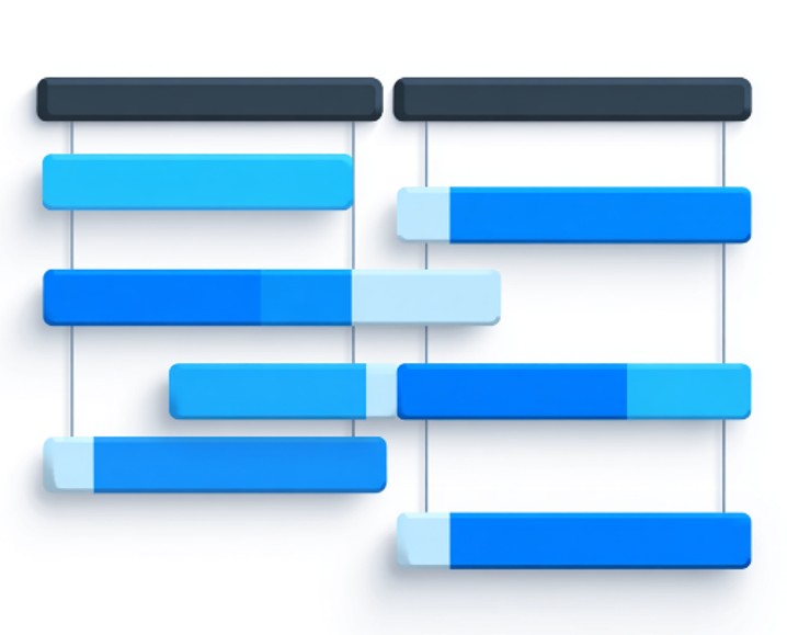
Visual Thread Scheduling Automatically Deployed Across DriveOS
Engineers can define thread scheduling parameters, such as period, runtime budget, and deadline, directly within Simulink, using simple visual scheduling blocks. They can explicitly model each control task with its timing behavior, eliminating the need for separate configuration files or manual OS-level tuning
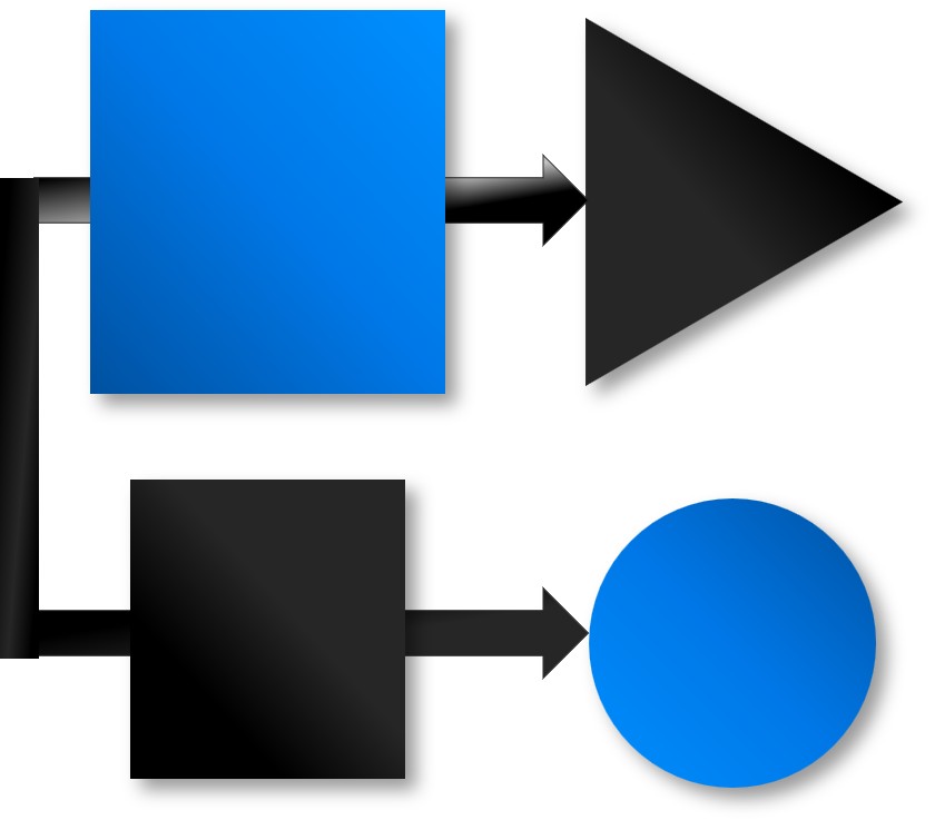
Seamless Communication Between Control Modules
In modular control systems, communication between components is a core part of system design. In DriveOS, different control modules may run in isolated sandboxed domains to preserve fault containment. DDE simplifies coordination between these modules with graphical modeling of real-time data exchange, whether engineers need guaranteed delivery or just the latest value.
Real-Time CAN I/O, Unified Over USB
The platform enables the vehicle control system to interface with a wide range of existing hardware — including supplier ECUs, test equipment, and legacy modules — without custom firmware, intermediate gateways, or one-off interface code.
Drako Design Environment provides native graphical building blocks for working with CAN buses.
System-Scale Deployment with End-to-End Timing Guarantees
Once a control system implementation is complete, Drako Design Environment automatically packages all components — including RTOS and Linux domain logic — into a single, versioned binary for deployment across the vehicle platform.
This unified deployment maintains strict domain isolation, streamlines integration testing, and supports rapid iteration while preserving timing and integration guarantees.
Hardware & Software Reference Portfolio
Drako offers a portfolio of hardware and software reference implementations that accelerate vehicle control system development by providing proven, reusable designs. Each example applies best practices for modeling, scheduling, and I/O configuration using DDE.
OEMs can adapt these assets directly into production programs or use them as structured templates when developing new control system components.
Hardware Reference Implementations
Drako provides several control system reference implementations that are ready to run under DriveOS with real-time behavior, scheduling, and I/O mappings already configured for immediate evaluation.
Engineers can use these modules as drop-in starting points for production programs, adjusting them to match specific architectures, signals, or actuators.
The implementations include:
- CAN & LIN
- Dash
- Pump driver
- Front & rear body controllers
- Door module
- Seat controller
- High power driver
- USB switch
- USB hub with power control
- PD hub
Software Reference Implementations
Drako’s software references extend DDE’s core control system workflow with tools for protocol translation, system abstraction, diagnostics, and interactive developer tooling.
The implementations include:
- Protocol adapter – Encodes and decodes custom or standard message formats over USB or socket interfaces.
- Firmware controller – Simulink‑modeled logic for coordinating with external MCUs that communicate with DriveOS.
- Socket gateway – Bridges TCP/UDP traffic into DriveOS domains for remote access, logging, or test integration.
- Configuration app – Supports runtime parameter tuning without modifying Simulink models, so engineers can iterate on behavior without rebuilding control logic.
- User interface app – Provides dashboards for visualization, monitoring, and command control during development or validation.